LEVELLING IN DETAILEverything you need to know about flatteners and levellers for coil processing • Part 1 • Part 2 • Part 3 • Part 4
Part 1 This is article is part 1 of a four-part series covering flatness and stability in cut-to-length, slitting, and tension levelling operations. This article covers how flat rolled metal gets unflattened, including the 3 categories of defects, how defects are created at hot and cold mills, and how coil processors also create defects.
To maintain material quality, first we must understand flat-rolled metal defects and how people and processes can cause them. Types of Shape Defects Three categories of flat-rolled shape defect exist, and resolving each requires a different approach and equipment configuration. In ascending order of complexity, the three categories are: 1. Surface-to-surface length differential. This includes coil set (see Figure 1) and crossbow (see Figure 2), which are related problems.
Edge wave, buckles, and camber are easy to understand. Twist is a little more difficult to visualize as an edge-to-edge length differential issue. If we unwind a twisted strip, we'll see that the edges and centre have different lengths, depending on the geometry of the twist, or helix. Twist is not simply coil set up on one side and down on the other side. A twisted strip has a side-to-centre-to-side length differential that, unlike edge wave, continues all the way across the strip. 3. Surface-to-surface thickness differential, or crown (see Figure 7). This is a common problem for slitters, and it will be discussed in Part IV of this article. Flatteners or levellers can't reduce crown significantly because their work rolls are offset. It takes a rolling mill with opposed rolls to do that. This article discusses the causes of crown, but not how to eliminate it. Sources of Shape Defects
The producer mills would like to make crown-free flat-rolled coils every time if they could. If they miss that goal, they much prefer a thicker centre for tracking purposes, so the coil runs straight through the mill stands. If the edges are thicker than the centre, the coil won't go straight.  At the Hot Mill At the Hot Mill
At the hot mill the crown or thickness profile can be changed without changing the shape or flatness, and vice versa. Hot mills try to get the relationship between crown or profile and shape, but achieving both perfect shape and perfect crown control is almost impossible. With new automatic gauge control (AGC) technology, the mills are doing much better, but perfection remains an elusive goal. At the Cold Mill At the cold mill, every time we change the thickness profile, we also change the flatness. The cold mill roll gap should start out being set to the same profile as the crown of the incoming hot mill product. Then, as the cold mill gap is adjusted to reduce the crown, the coil also will come out flat--if the hot mill got the relationship between crown and flatness right to begin with. If the cold mill rolls or hot mill coils have too much crown, the mills will roll out the centre, creating centre buckle in the process (see Figure 8).
Mill work rolls and backup rolls bend and compress under the vertical loads it takes to reduce plate or sheet coil thickness. In theory, if the work roll surfaces were absolutely parallel, the top and bottom surfaces of the rolled product would be parallel--no crown. But the fact is that everything is deflecting under the rolling loads and so it doesn't work that way. The mills deliberately crown their work rolls slightly larger in the centre to allow for deflection and compression under load. The amount of roll crown that is added is a compromise, a best guess. In addition, mills can control the gap profile by bending these huge rolls or by expanding them with hydraulic pressure like a huge steel balloon.
The hot mill's strategy is to get the relationship between crown and shape correct so that they will both come out right in cold rolling. If that sounds difficult, it is! The tension on the coil strand through the mill also affects the thickness reduction at the mill roll. It shouldn't surprise us then if that the heads and tails of the mill coil are thicker than the middle because they did not have full tension. Problems Aren't Only in the Mills Do you remember Pogo? Pogo was a small opossum and a great philosopher--in the Sunday newspaper comics! He once said, "We have met the enemy and they is us!" Well, sometimes we are our own enemy--because shape defects can be induced at any stage in processing of the coil, and we're all part of that.
Where does coil set come from? It's in the coil! Coil set should be more pronounced on the coil's inside wraps and less on the outside because the inside bend radius is smaller. In fact, it's possible to have residual reverse coil set in the outer wraps from the original master coil before it was swapped head to tail in some previous operation. We also can induce reverse coil set during our own uncoiling process by backbreaking the material over a small breaker or pass line roll. How many coil processors can use a 60,000-pound master coil straight from the rolling mill? Somebody has to pickle it, anneal it, coat it, slit it, and perhaps cut it to a smaller OD. Flatness problems can arise anywhere along the line. Here are some examples of how this can happen.
I watched an aluminium mill tension levelling coil on a new line. It was dead flat coming out of the leveller and then they recoiled it, under a lot of tension. The coil was crowned, meaning that the centre of the strip was thicker, so the centre of the coil on the rewind arbor had a larger OD. Big surprise! The operators were rewinding the coil over a barrel. That was pulling centre buckle back into it! Flatness inspection had been done after levelling and before rewinding. QC insisted the material was dead flat. The customer said it was buckled when he unwound it. Engineering wanted to know about the material's "memory" or trapped stresses. Everyone was wrong.
We found that the backup roller pins were badly distorted and bent. The side frames were sprung. No amount of training was going to help them. Worse yet, the line management personnel didn't understand that they were the culprits. Some years ago I watched a badly maintained service centre slitter producing "snakes." The recoiler arbor had been bent and was wobbling several inches as it rotated, pulling an oscillating camber into each slit mult coming from the tensioning device. Any rolls in the system, such as pinch rolls, slitter arbors, flattener rolls, leveller rolls, and, of course, feeder rolls, that deflect or that are misaligned can produce edge wave or even camber. These rolls can put uneven pressure on part of the material and destroy the coil shape in the process.
It's surprising how many times I've found that flattener and leveller rolls haven't been reground or recalibrated in years, if ever. It's surprising how many line operators don't have access to information about machine capacities or to either nominal or actual material yield strengths of the metals they are processing. It's surprising how many line operators have had no training on the meanings of these critical numbers. It doesn't make sense to talk about equipment upgrades if the people running the equipment don't understand the equipment they use now. Before we start talking about new equipment, let's see what we can do to get the best out of what we already have. I'll discuss this in Parts II and III of this article series. Remember, we need to make good stuff out of the bad stuff. Not the other way around.
Part 2 Flattening solutions and the anatomy of a bend in flat-rolled metals.  
Figure 1
Figure 2
Figure 3 Metallurgically, most metals that coil processors deal with act similarly, as does the equipment used to fabricate those metals. A stress-strain curve, such as the curve plotted for carbon steel in Figure 1, shows the relationship between the force on a metal and the metal's change in dimension. The vertical axis in Figure 1 represents the amount of stress, or force, on the metal; the horizontal axis represents the amount of strain, or elongation or stretch. The metal stretches like elastic or rubber in the elastic range. The graph in Figure 2 illustrates that 1 pound of pull, or stress, always causes the same amount of stretch, or strain, for a given metal and cross section. Two pounds of pull results in twice that much stretch. If we pull it any amount up to the yield point and let go, it snaps back to its original shape, like a rubber band. Flatteners and levellers (as well as roll formers and press brakes) don't make any permanent change in the shape of the metal if its yield point isn't exceeded. The metal goes right back to where it was, like an old-fashioned screen door spring. Once the metal is stressed past the yield point, it's in the plastic range (see Figure 2). What happens when the metal is stretched into the plastic range and then released? It does not go back to its original form. It may spring back slightly, but not back to zero. Metal stretched past its yield point results in a permanent change in shape, or permanent set. This occurs in a flattener, leveller, or press brake die. It's also what has happened to a "sprung" machine frame. If material is pulled or stressed past its yield strength all the way to the ultimate tensile strength (see Figure 1), it will fracture or break. That is exactly what happens when we slit, stamp, or saw metal. It's also what happens when a crankshaft or die breaks. Rules of Thumb The rule of thumb for eliminating simple coil set is to stretch the upper and lower surfaces an amount equal to two yield strains (see Figure 3), or twice the distance from zero to the yield point. This produces permanent yielding in the outer 20 percent or so of the top and bottom surfaces of the metal. The central 80 percent of the thickness remains unchanged. Thus, coil set elimination is strictly a surface issue. The rule of thumb for eliminating crossbow is to stretch the upper and lower surfaces an amount equal to four or five yield strains past the zero point (see Figure 4). Poisson’s ratio for steel is about 0.3. To get enough crosswise elongation to eliminate crossbow, the surfaces must be elongated lengthwise 1 divided by 0.3, or about three times as far past yield. This is how we get the four to five yield strain rule. This produces permanent yielding in the outer 80 percent or so of the top and bottom surfaces, with only the central core -- 20 percent -- remaining in the elastic range. 
Figure 4
Figure 5
Figure 6 The rule of thumb for eliminating buckles or waves on a leveller is the same -- four or five yield strains. The difference is in the leveller’s adjustable roll bend, which flatteners don't have. Levelling Other Metals Based on the flattener or leveller manufacturer's capacity specifications for processing steel, can you also process other metals at the same yield strength and thickness? Don't assume that you can! Aluminium that has the same yield strength as steel, for example, requires more horsepower to level it. Aluminium is more elastic than steel, so it stretches more than steel would with the same amount of force (see Figure 5); that is, it has a different modulus of elasticity. A flattener or leveller must be set deeper than for steel because aluminium must be stretched farther to get past its yield point. Here's the rub: Horsepower can be described as how hard and how far metal is stretched in a given period of time. Stretching aluminium farther at the same line speed and yield strength takes more horsepower. The structural load on the machine will be the same, but the horsepower must be greater. Ask the manufacturer of your levelling equipment before testing its limits on aluminium. The Bending Process The bend radius of the metal going through a flattener or a leveller is determined by the machine's roll configuration, diameters, and spacing. Metals are basically crystalline in structure. However, engineers talk about the inner, outer, and central, or neutral, fibres because it helps us to visualize what's going on (see Figure 6). What happens when flat-rolled metal is bent over a roll or die? Its outer surface, or outer fibres, is elongated enough to exceed the metal's yield point; otherwise, no permanent change will have been made. The centre of the cross section, the neutral fibber, is neither stretched nor compressed. The farther the surface fibres are from this neutral fibre, the more elongation or compression will occur for a given bend radius. That is simple geometry. At some distance from the neutral centreline on the top and bottom of the bend the material yield point is exceeded and the material is in the plastic range. The middle is still in the elastic, or "springy," range. Effect of Thickness The amount of elongation for the bend over the radius resulting from a particular roll configuration is a function of the distance of the metal’s surface from the neutral fibre. The thinner the metal, the less surface yielding occurs -- to the point at which no yielding and no change occur. The thinner the metal, the less is the distance from the upper and lower surfaces to the neutral fibre and the less surface yielding occurs -- to the point at which no yielding and no permanent change in shape or flatness occur. This is in fact the minimum thickness limit. The thicker the metal, the greater the distance from the upper and lower surfaces to the neutral fibre, the more elongation will occur, and thus the greater the force required to make the bend. Therefore, the upper thickness capacity limit for that machine is the machine's structural deflection under load. This becomes the maximum thickness limit.
Figure 7 The different colours in a computer-generated analysis of the stress or strain in a piece of metal shown in Figure 7 tell us how much force or how much stretching is involved in bending the material over a roll. Half of the material is in compression and half is in tension. A neutral fibre goes down the middle. It's just as simple as that. The stress, and therefore the strain or stretching, is completely symmetrical about the neutral centre fibre. So far we've considered only one bend. Now consider a flattener or leveller with multiple, reversing, and up-down bends. First it stretches the top and compresses the bottom. On the second bend it compresses the top and stretches the bottom, then reverses that again on the third bend, and so forth. The neutral fibres are always right down the middle. They're not stretched past their yield points, so no permanent change occurs in the centre of this cross section. The change, past the yield point, is strictly a surface effect. Effect of Adding Tension Most cut-to-length or stamping press feed flattening or levelling applications are performed without tension, except possibly for steering. Putting significant tension on the material as it goes through the flattener or leveller has the effect of moving the neutral fibre toward the inside of the bend. The added strip tension then adds to the tension in the outside of the bend and subtracts from the negative compression on the inside of the bend. The result is less compression on the inside and more tension on the outside. The neutral fibre -- the part that's neither compressed nor stretched -- moves toward the inside radius of the bend. Why is this important?
Figure 8 Consider the second computer analysis as shown in Figure 8, this time with tension on the strip. This stress pattern is not symmetrical. When the material goes through a leveller or flattener under tension, the first bend gets much more tension on the top and very little compression on the bottom. In the second bend this is reversed -- very little compression on the top and a lot of tension on the bottom. The process is reversed again and again as the material passes through the leveller. By the time the material comes out the exit end, more, or possibly all, of its cross section has exceeded the yield point, not just on the surfaces. All fibres, top to bottom and side to side, have been elongated past their yield points. This results in even flatter and more stable material. It also extends the lower capacity range of any roll configuration. Tension-assisted flattening or levelling has been used in some cut-to-length lines and slitting lines. It forms the basis for tension levelling technology. Trapped Stresses and Stability Producer mills and subsequent processors unwind, roll, heat, cool, and rewind the metal. They're trying to control thickness, flatness, and perhaps other parameters to comply with the customer's requirements. Unseen but very real opposing forces are trapped inside the metal. No apparent reaction may appear until we machine, stamp, or heat the metal. These processes can break or release some of the trapped opposing forces. Then the material changes shape all by itself. Sometimes the metal just relaxes. We know that the initial trapped stresses in a coil are random and varying from head to tail and side to side. A spread-centre flattener produces a surface yielding only. A close-centre flattener or a leveller, without tension, at four to five yield strains overcomes the previously trapped random stresses with new but uniform stresses in all but the core fibres. With tension, a close-centre flattener or leveller overcomes most or all the previously trapped random stresses top to bottom. Note that I did not say that trapped stresses are completely eliminated in the levelling process. Trapped stresses will be more consistent and considerably reduced if we work it hard enough. The result is significantly more stable material.
Part 3 How coil processors can make metal flat so it stays that way
We also need to clarify nomenclature. I'm not sure what the difference is between a flattener and a straightener. No two people I've talked to seem to agree on a definition. In Europe they both are called levellers. Further, all flatteners are not the same. In this article, I will define my own terms to describe the different equipment configurations. The Functional Difference Between Machines
Option No. 1: A non-backed-up spread-centre flattener for surface-to-surface length differential. This machine is designed for removing coil set only. Rolls are configured to bend the material enough to achieve two yield strains, or twice the distance to the yield point in the outer fibres, or surfaces, of the metal. Thus, elongation past the yield point is strictly on the surface. If we close the entry roll gap to get more bending, the unsupported centre of the work rolls may deflect, putting edge waves into the metal.
To eliminate crosswise crossbow in addition to lengthwise coil set, this flattener configuration must be designed to produce four to five lengthwise yield strains in the outer fibbers of the metal. Option No. 3: A precision roller leveller for both surface-to-surface and edge-to-edge length differential.
Unlike a flattener, leveller backup roller flights can be vertically adjusted independently of each other, so the work rolls can be bent deliberately in a controlled manner and held there under load. On a backed-up close-centre flattener, the backup rolls are there to keep the work rolls from deflecting. A leveller, in the neutral setting, like a backed-up flattener, can eliminate surface-to-surface length differentials such as coil set and crossbow. Edge wave and centre buckle are edge-to-edge length differential problems. For that we need to differentially elongate the centre or the edges of the flat-rolled materials so that they are all the same length. This requires controlled work roll bend. Of these three options, only a leveller with adjustable, independent backup rollers can control or eliminate edge-to-edge length differentials. Machine Settings, Entry to Exit Gap
The entry gap setting for any material thickness and yield strength usually is supplied by the equipment builder or designer. The entry gap for a spread-centre flattener generally will be relatively light. The entry gap for a close-centre flattener or leveller will be deeper. In all cases, the initial exit gap setting should be at material thickness. At one operation I visited, operators were instructed to close the entry gaps enough to avoid slipping when pulling slit coil off an unpowered uncoiler. In all likelihood, that setting would be much too light to get much work out of the equipment. I recommended they refer to the equipment builder's manuals for the proper settings. Once the entry roll gap has been set, final adjustment for lengthwise coil set, up or down, is done at the exit. If, as is usually the case, the last work roll is on the bottom, closing the gap slightly will induce additional upturn. Opening the exit gap slightly will give some downturn. If the last roll is on top, the opposite will be the case. Machine Settings, Edge-to-Edge Neutral Setting. In the neutral setting, work rolls are straight and parallel, and the backup Leveller Roll Bend Setting. Roll bend is available only with the leveller configuration. It is what makes a leveller a leveller. As a practical matter, most full-width, light-gauge levellers have from seven to 11 flights of entry-to-exit backup rollers, giving the operator considerable area control over waves or buckles in the incoming material. The number and spacing of the backup roller flights are important. The more flights and the closer the spacing, the better. I've seen a machine with too few flights to hold the work rolls straight under load. The unsupported work rolls deflected between the flights. To Stretch the Edges. In the case of centre buckle or long centre, you need to stretch the edges until they are the same length as the centre (see Figure 5). Set the backup rollers so the work rolls are tight on the edges and loose in the centre. With the proper roll gap setting, the coil will not slip over the work rolls. The work rolls are all exactly round. The coil has to go a greater distance on the outer edges than in the centre because the sink, or roll, mesh is greater on the edges. This means that we will stretch the edges in a controlled manner.
Four-high, Five-high, and Six-high Levellers
If such marking is a problem, a six-high leveller may be required (see Figure 8). Full-length intermediate rolls support the work rolls, and they in turn are supported by flights of backup rollers. A burnish mark on an intermediate roll does not transfer to the work roll -- no striping problem! There is one drawback: This configuration can be very stiff. Roll bend may not be sufficient for optimum shape control.
About Leveller Capacity Your equipment builder should supply design capacities and settings for its machine for given materials, yield strengths, and thicknesses. But what happens when we run materials beyond these capacity limits? If the material's thickness is below the machine's minimum limit: We will not flatten or level it. There is insufficient fibre elongation to make any permanent change in shape. No damage will be done to the equipment. Also note: • The lower thickness capacity rises in proportion to the yield strength. • There is another lower-limit issue: stiffness. If the material is so thin or soft that it does not push up and down on the leveller rolls hard enough to cause sufficient friction to avoid slipping over the rolls, the leveller cannot provide differential, side-to-side elongation. This can be the case with some perforated metals. Perforating weakens the material and thus raises the upper thickness capacity. It is less obvious that with perforated metals the lower capacity may also rise because of the lack of stiffness. If the material is very narrow: We run the risk of concentrating the entire load on too few backup rollers. You may bend or break the rollers or their supports. This is why there is no real narrow-thick capacity on this type of equipment. If the material's thickness is above the machine's maximum limit: Loads on the equipment increase very quickly. Vertical separating forces between the upper and lower banks of work rolls are a function of the square of thickness. Don't do it! You may bend or otherwise permanently damage the machine's supporting structure. It is not a matter of how many times it has been overloaded. Once can do the job. If the material's actual yield strength is higher than the machine's design yield: Machine loads increase as a function of the square of the actual yield strength. Notice that I refer to actual yield strength, which may be much higher than the nominal yield strength. This is an easy trap. Many grades of metal have only minimum yield strengths, but their actual values can be 15 to 25 percent higher. That can be tough on the levelling equipment if you also are approaching maximum thickness at the same time. As an example, if your machine's design capacity is based on 40,000 pounds per square inch (PSI) yield but the actual yield strength is 60,000 PSI, that is a (60/40)2 ¥ 100 = 225 percent increase in the machine load. Maximum thickness capacity should be reduced by 100 divided by 225 percent, or by 44 percent. The minimum thickness would be increased by (60/40) ¥ 100 = 150 percent. The minimum thickness rises and the maximum falls. You cannot produce four to five yield strains and cannot fully level any thickness outside the revised yield range on this particular machine. You may be able to produce sufficient yield strain to remove coil set.
Part 4 New applications and options in flattening and levelling The best way to eliminate defects in coil shape is to buy prime material. What you get out of any leveller, flattener, or tension leveller is affected by the flatness of the material you put into it.
Preventive Maintenance Shape control equipment—flatteners or levellers—generally is the heart of most manufacturer's or service centre’s coil processing and feeding lines. Don't overload it. Use proper settings. Maintain it. Align it properly. Keep it clean and calibrated. The surfaces of flattener or leveller work rolls and backup rollers should have been case-hardened to reduce wear. However, they can pick up slitter slivers, aluminium oxide, spelter, mill scale, and grit.
Note that this roll cleaning can be dangerous; employees must be careful not to get dragged into the machine. An intriguing option, available from one of the leveller manufacturers, is to perform this roll cleaning by remote control so that operators aren't put at risk (see Figure 2). Work rolls and backup rollers are expendable tooling. Regrind your work rolls more rather than less often. Work rolls and backup rollers must be reground as matched sets. If this is done regularly, only a minimum of material has to be removed with each regrind. On that basis you might get 10 to 12 regrinds out of a set.
Most major leveller manufacturers offer an optional work roll cassette or "works in a drawer." You can pull a roll cassette in and out of the leveller as a unit. You may have more than one cassette. Flip the cassette open and clean it offline. This is generally an expensive option. We sometimes recommend it for a line that's going to run continuously, three or four shifts. For a conventional service centre cut-to-length line, this expensive option may not be justified. For highly utilized toll processing operations, however, it might be worthwhile. Another maintenance option is computer fault-finding diagnostics, and most new coil lines have this feature. I would not buy a coil line without it. The control monitor can tell you what's wrong with many items. In fact, it generally tells you what's going to go wrong before it does go wrong. For instance, it can warn of drive motor and other overloads. If the machinery is approaching low oil level or low oil pressure, the monitor might warn you before a bearing freezes. Or it may tell you which circuit board in which panel is in trouble. Other Options on New Levellers Optional features on new levellers include automatic roll positioning for each thickness and material so the operator doesn't have to remember the settings. The computer remembers specific coils if you want to do rebooks. Note that for any given coil, the operator still has to make minor equipment adjustments to produce dead-flat material. The addition of an automatic roll calibration control option simplifies calibration after roll changes to adjust for the newly reground roll diameters. Recalibration of a wedge-type mechanical leveller should be necessary only after roll regrinding. Regular calibration of a directly positioned hydraulic leveller apparently is required to compensate for drift. Cut-to-length Line Configurations The most obvious and common application for levelling equipment is in a cut-to-length line. In some very old lines, the leveller is placed after the shear, which means material is levelled in plate or sheet form. While this remains typical of many European lines today, it does have some technical problems. In North America almost all modern lines level the coil before the shearing operation. The arguments about the pros and cons of this are exhaustive, but I think North America has it right. Except on some very heavy-gauge lines, you do not want to stop and start the leveller every time you feed to length into the shear, because this causes excessive wear on the leveller’s drive train and probably leaves set marks on cold-rolled surfaces. Most lines use looping pits or flying shears with the leveller going slow then fast. Since levellers have a limited capacity range of about four times the maximum or minimum material thickness, it is common for two levellers—a big one and a smaller one—to be used in a cut-to-length line to extend capacity range. Logic says that you then would have a two times four equals eight times the maximum or minimum thickness range, but that is not the case. Since minimum thickness rises with yield strength while maximum thickness is reduced, these lines need a considerable capacity overlap between their two levellers at nominal yield. Remember that the equipment uses the actual yield strength, not the nominal. The practical range for two levellers is closer to six times maximum or minimum. Some builders have offered a single leveller with two roll cassettes having different roll diameters and spacing. This arrangement still gives a capacity range of about six times maximum or minimum. It is also very complex and can cost almost as much as two separate machines. A European builder has proposed a multi-roll machine with vertically adjustable odd and even work rolls instead of the conventional, inline upper and lower banks. By backing off every other roll, the machines double the roll centres for the thicker range of materials. Some complexities remain in arranging backup flights. Most operators tell us that it takes several hours to swap cassettes. There is also a question about placement of an edge trim slitter in a cut-to-length line. One argument is that it should be after the leveller for accurate width control. The contrary argument is that the edge trim slitter causes edge turn-down and thus should be before the leveller. I agree with the latter, provided there is a hefty centre hold-down roll at the edge trimmer to avoid crossbow during trimming.
Tension-assisted levelling lines can process heavier thicknesses than are practical with tension levelling. The issue is this: How deep past the yield point do we get penetration into the cross section? Immediately following the cut-to-length line leveller, a pair of large driven pinch rolls provide pulling tension, thus moving the neutral fibre closer to the inside radius of the metal's cross section in the leveller as discussed previously (see Figure 3). The addition of some tension extends the maximum capacity upward and the minimum capacity downward. This is designed to provide increased levelling capacity range, increased stability, and improved levelling.
A number of recent-model coil lines for heavy-gauge hot-rolled plate include a temper mill just before the leveller (see Figure 4). The effect on material surface quality, flatness, and stability is significant. This is especially important for applications in which some of the new technologies, such as laser cutting, are to be used. The material must stay flat during and after the cutting process. The temper mill cannot get the material as flat as a corrective leveller can, and the leveller cannot get the material as stable or provide as fine a hot-rolled surface as the mill can. But the two together can produce some superb product. Slitting Line Configurations Including Inline Levelling When we slit a coil with crown or a thick centre, the centre coils on the recoiler will have a larger OD than the outer coils. That causes the centre strands to wind faster and the outer strands to wind slower and looser. The outer coils may be so loose that they are dangerous to handle.
A friction drag device following the slitter puts tension on all the strands, or mults, going onto the rewind mandrel. The apparent excess length on the outer, looser slit strands is allowed to hang down into a looping pit (see Figure 5) between the slitter and drag device. All strands going onto the recoiler are reasonably tight.
Levelling in a Slitting Line Several different slitting line configurations are available that include corrective levelling after the slitter and before the recoiler. Synchro-Wind and Kor-Flex are similar (see Figure 6). Both employ a pit, drag device, leveller, and then recoiler. Neither significantly elongates the strands.
The line operator can stand at the main control panel, away from the dangerous recoiler nip, and change the amount of elongation in the tight mults so they all wind tightly with the flick of a control lever. Just as with a roller leveller, the line operator can elongate some parts of the coil relative to other parts by adjusting the backup roller flights to deliberately vary the sink or penetration of the upper and lower work rolls at different points along the face of the machine. Tension Levelling Tension levelling is an effective tension-assisted levelling method. The coil is put under significant tension between pull and drag bridles placed before and after the specially designed roller levelling device (see Figure 8). With tension levelling, all parts of the metal are pulled past the yield point, top to bottom, edge to edge. The full cross section is elongated a fraction of a percent. All the previous history of trapped stress is deleted. The material should be dead flat and relatively free of internal stresses.
How Flat Is Flat? Measuring flatness, or even describing it, has been a tricky issue. Out-of-flat tolerances have been described by ASTM International and ANSI standards as a maximum wave height in 8 feet without any mention of the number of waves. When we're trying to fit up a fabrication, it makes a lot of difference whether we are talking about a 1/4-inch rise in 8 ft. or in every 8 in. We find increasing acceptance of the I-unit flatness designation (see Figure 9), which takes into account both wave height and wave length. Producer mills say they can get less than 15 I units of flatness coming off the cold mill. With a temper mill, they can get less than 10 I units. A roller leveller, a Strand Extensioner, or a tension leveller produces less than 5 I units, and maybe less than 1 I unit. That's a big difference in flatness.
|
 Does your coil processing operation preserve or improve quality? Do you struggle just to keep the quality the mills put into their flat-rolled products, or do you have equipment that can upgrade quality and add further value to your coil processing operations?
 2. Edge-to-edge length differential. If the edges are longer than the centre, you will have wavy edges (see Figure 3). If the centre is longer than the edges, you will have centre buckle (see Figure 4), sometimes called oil can or canoe. This category of defect also includes camber (see Figure 5) and twist (see Figure 6).
 If the cold mill rolls or hot mill coils have too little crown, the mills will roll out the edges and create edge wave (see Figure 9). This is fairly common in mill master coils.
 You've probably seen the pictures of the mill control pulpit with all its controls and computer monitors. Every time the operator pulls a lever, he changes what's going on at that mill stand and, therefore, the amounts of deflection.
 How many metal buyers would like to specify coils without coil set? The problem is that coils are in coil form. Most coils have a 20- to 24- inch ID. In most cases, unless the metal is very thin or very hard, coil processors put coil set back into the material during the recoiling process. The producer mill's levelling equipment can make the material dead flat, but then the metal is recoiled for shipment to you, and that puts coil set back into it.
 I once inspected a brand-new steel mill tension leveller in a hot-dip galvanizing line. The metal coming out of the zinc pot and going into the leveller looked terrible. It was like a bright, shiny mirror coming out of the tension leveller. Then it went into a 40-year-old, misaligned accumulator before being rewound or sheared to length for customers. The accumulator destroyed the shape quality. The shipped coils and sheets were not flat. The line operators were frustrated because they knew about the problem but could do nothing to resolve it. My heart went out to them.
 I was asked to provide operator training on an old roller leveller that had been very badly overloaded. The service centre owner told me that the work rolls had just been reground and the machine recalibrated. His men still could not get flat material out of it.
 It's surprising how many operations do not perform preventive maintenance or calibration and realignment. "If it ain't broke, don't fix it." Right!
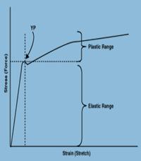
 Option No. 2: A backed-up close-centre flattener for surface-to-surface length and width differential.
 Like the close-centre machine, a precision roller leveller is also designed to produce four to five yield strains in the outer fibres of the metal. Again, yielding is more than a surface effect.
 The process of setting the entry and exit work roll gaps is similar for all three machine types. In general, the entry gap is set tight, feathering out to approximately material thickness at the exit gap (see Figure 4).
 rollers are in a straight line, across the face of the machine. This is the setting if coil set or crossbow is the only shape problem. In practice, this would be the case with either a fixed backup flattener or an adjustable backup leveller.
 To Stretch the Centre. In the case of edge wave, or loose edges, you need to stretch the centre until it is the same length as the edges (see Figure 6). Set the backup rollers deep in the centre and shallower on the edges. Since the material will not slip and it has to go farther in the centre, we will stretch the centre and reduce or eliminate edge waves.
 The simplest leveller configuration is four-high (see Figure 7). This is the most flexible configuration regarding shape control. However, the backup rollers may burnish the surface of the work rolls. That may leave a visible impression or stripe on some sensitive materials. On polished stainless or aluminium, or on class 1 automotive exposed stock, this surface imprint can be objectionable. You can't measure it, but you can see it -- it will show through paint or other coatings.
 Some processors compromise with a five-high leveller. The adjustable backup flights for cold-rolled coils usually are on the bottom work roll bank. The intermediate rolls on the bottom are eliminated, and the full-length intermediate rolls on the top are retained. This means we won't stripe the top surface of the coil, but we may stripe the bottom. As a rule, only one side of the coil stock is prime. With a five-high leveller, we have both the flexibility for area control and no striping on at least one critical side.
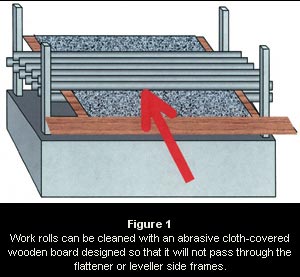 To clean work roll surfaces, put a Scotch-Brite® pad, carpet, or other cloth fastened to a T-shaped plywood board (see Figure 1) into the slowly turning but empty flattener or leveller roll nip and hold it there. The T should be wider than the machine frame so the board will not pass through.
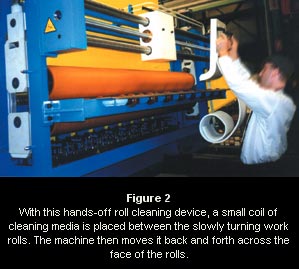 Light-gauge cut-to-length line rolls in service centres could be reground every six to 12 months. Slitters run a lot more miles of metal each day. Toll processors' slitting line levelling rolls may need to be reground every 10 to 30 days for use with sensitive-surface materials.
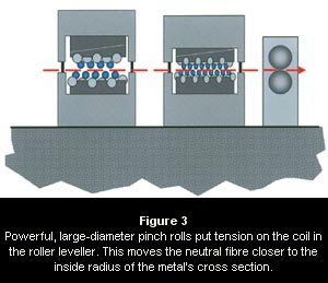 Capacities for Processing Heavier Thicknesses
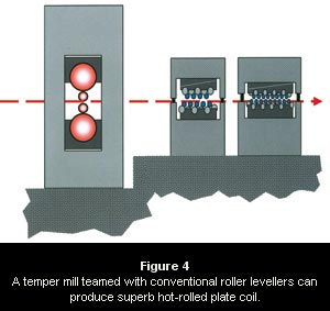 A Temper Mill With Roller Levelling
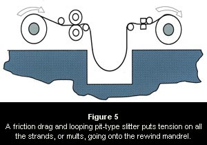 Years ago slitter operators stuffed paper into these outer coils so that they pulled tighter. That was very dangerous. ANSI B11.14 (American National Standards Institute) standards for slitting line safety, which apply to line owners and operators, specify you shall not stuff paper unless the line is stopped or the operator is protected. Paper stuffing no longer is necessary. Slitting technology has evolved with the drag and pit configuration.
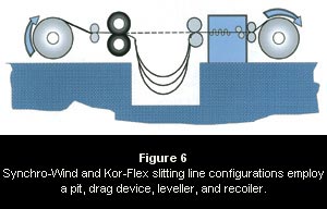 This solves the differential strand rewind issue but may introduce new problems. Aside from operators having to dig, clean out, and walk around the pit, the friction drag devices themselves can scratch or imprint the coil surface. In addition, coil shape and straightness cannot possibly be better than the master coil. Levelling individual narrow mults after slitting is neither mechanically nor financially feasible.
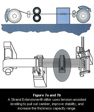 The Strand Extensioner®, on the other hand, employs tension assist in the levelling process, which pulls out most of the camber, improves stability, and increases the thickness capacity range (see Figure 7). Significant necking, or narrowing, of slit strands has not been a problem. Since no friction drag is involved, the possibility of surface scratching is significantly reduced.
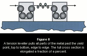 Tension levelling usually is restricted to gauge thicknesses of metal. Because of the massive equipment and horsepower required, this process usually is not practical for thicker, hot-rolled plate coils. However, more and more service centres are using tension levelling lines to process cold-rolled steel and aluminium products.
© 2009 AP Design